
 Welcome back. If you haven't already, feel free check out the first half of this build which detailed the goals, design, and cockpit work. This second half will focus on the electronics and the rest of the overall building steps. Before we continue on with the assembly steps, I am going to take some time to explain my electronics setup and execution. I figure it will be better to get an understanding of what I am doing now, rather than piecemeal as I go through the rest of the build.
______________________
Electronics
LED's are generally 3V, with 20mA current draw. When using a 9V source, LED's in parallel waste a lot of this current, and greatly increase the amount of wires hanging around. Ideally I wanted my schematic to be parallel series of 3 with a minimal resistor whenever possible. I was lazy in this build and kept the same resistor value for the series as the original parallel, but it works well enough with a healthy battery. Here is a rough schematic of what I went with. It is recreated from memory, so it may not be 100% what I used, but it gets most of it right. In particular I think I might have actually run a few of the Always On section in parallel rather than a series.
Take a look at this LED calculator that helped me start out the schematic.
It may not be obvious from above why certain paths are split up, so this should clear up the reasoning. It was because of space, specifically around the cockpit. Since that space was now used up, I needed to route a bunch of wiring around it to get to where it all needs to go. I decided to split the main wire right below the cockpit into 4, and route them into the right and left shoulders.
From there one line(green) serviced the Always On LED's, and (red) to the quick disconnect for the weapon. The other line(grey) heads out to the shield, and blue went to the first jetpack, and behind the cockpit seat to the other jetpack.

Here is a basic look at my workstation for soldering and assembling. The extra hand clips really help when trying to solder LED's in particular angles. My process was to strip off the insulation of my pre-wired and resistor for 9V LED's, desolder wires as needed. I would solder up my LED's one at a time in the series needed, and both insulate and put everything in place with hot glue. As nothing runs hot on this, I didn't fear any glue melting after the build was done. Hot glue also makes a nice light diffusing material. But it must be used only when you are sure you are done, as trying to get all the glue off to fix mistakes later is a serious pain. Order of operation really matters, as I cant close up sections until their required wires are through where they need to go and the electronics tested up to this point. This is why you will see the cockpit halfway assembled for half of this build.

______________________
Building the Bottom Half
The battery holder would be a part of the terrain that the Riptide would be standing on. I continued to test out dry-fitting the model and how it would be interacting with the base. I used a poster tack to keep the model relatively put together in this stage. It is tacky enough for basic holding, but won't stick when you start pulling it off.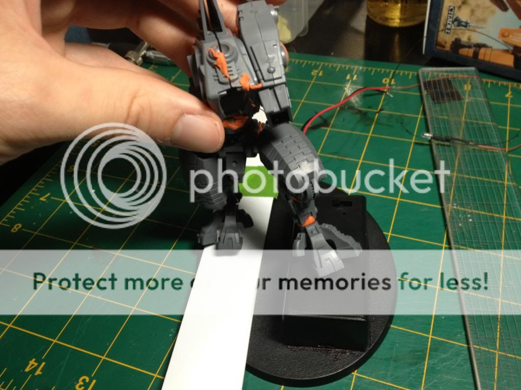
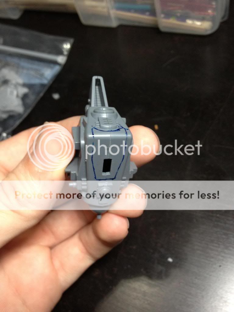
When I was ready to add in the battery holder, I made a simple outline and cut out the hole in the base with a sharp exacto. Extra spacing was filled in with a ring of plasticard to make the holder fit snug, and it was solidified with super glue.


From there I began populating the base with bits to mask the battery holder. I also decided to flip which direction the Riptide would be leaning, so the tank turret helped accomplish this and gave the piece a much higher vantage point. I don't normally like elevating my models too much from the base height, but this helped draw more attention to just how big this model is and kept focus away from the battery holder.


The left leg and feet was the first thing glued into place. Like all good Tau battlesuits, I mucked up positioning and broke the ankle. I'm used to this, so pinning wasn't a problem. It was probably for the best, as this would now be a solid stability point.


With the left leg ready, I began routing the main wires through the right side piece by piece. Through the tank, into the foot, calf, thigh, and then abdomen. I didn't need to glue segments as I went, as the wiring acted as a skeleton. I would solidify them later. I cut some corners with some wires showing, but they aren't noticeable in the final build.


______________________
Torso First Half
This is where I soldered in the leads that would go to the 4 LED locations. Between all the wires and the hot glue, this whole space was very cramped. Because of the wiring and to keep things open in case of troubleshooting, I left the cockpit incomplete until I finished both jetpacks.

______________________
Left Shoulder
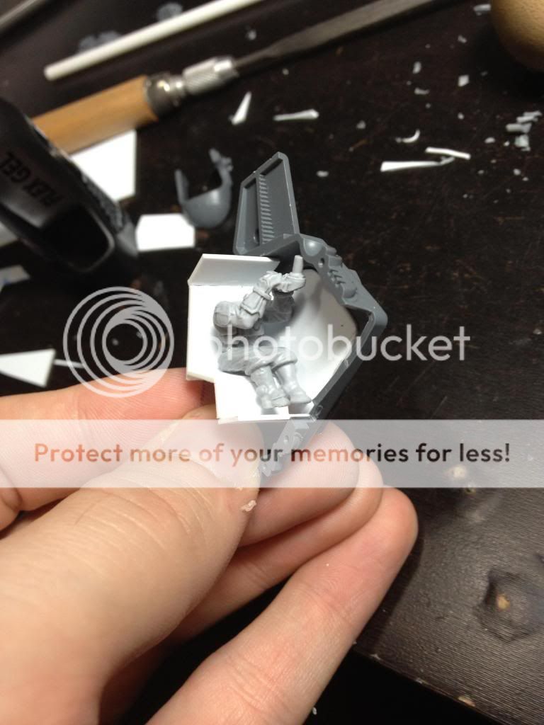
The front shoulder thrusters were fairly easy to do. I had already drilled out the front grill plate, and all I needed to do was drill a hole for the LED to fit through. I also painted the inside area around the LED with the turqouise that I wanted to show with the white lights. I think I actually snuck this one into a parallel wiring with the jet pack LED wire. All of the other continuous on LED's would draw from a right side shoulder wire.

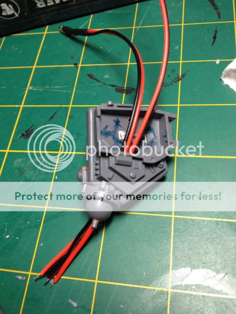
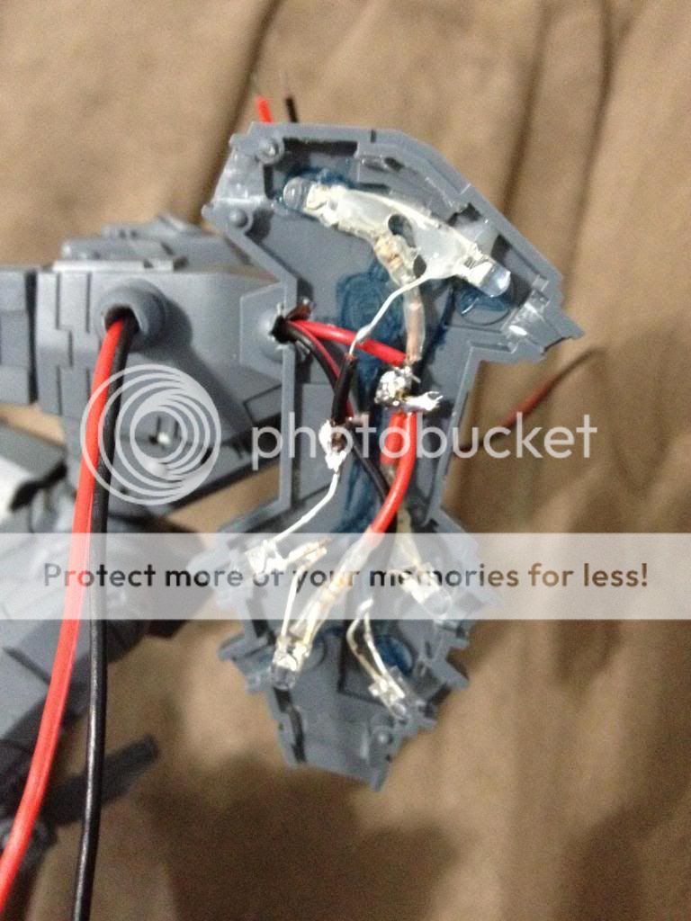
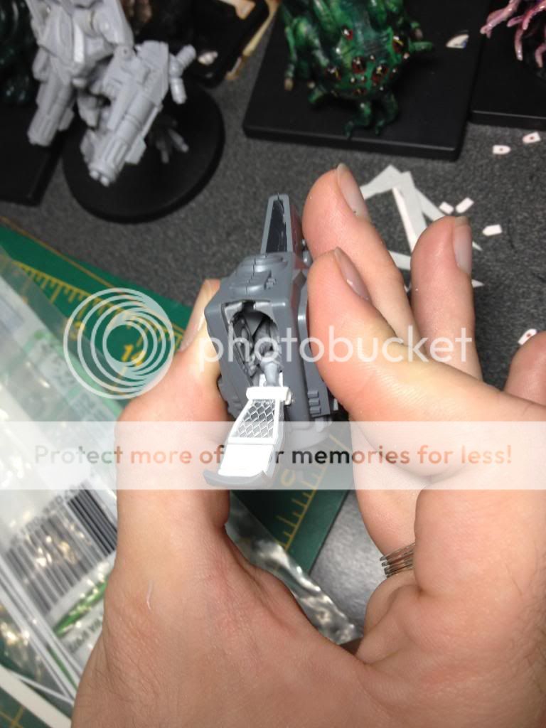
This side shows a lot more of what is going on in this shoulder. It's very busy. One of the main wires will go in on the switch and power the left jetpack. The wires going off screen will route behind the cockpit to the right jetpack so it is in parallel connection with the left (and shares the same switch). The hole in the middle is for the shield wire which will route straight on through the shoulder into the left arm. Excuse the fingernails, but it does help to have longer nails when pushing things into place with hot glue everywhere..

It was nice of them to build the shoulder with connections that fit the wires I need to route. It is a bit of tight fit on the jetpack side of this connection though, so I needed to shave out as much of the spot as possible to get the wires through.
Here the shoulder is coming together. All the wiring is in, everything clears and is glued down, so it is a matter of slowly closing it up without breaking anything. Sometimes you need to push around a wire or cut out some dried glue to force it closed. Having wires cut down to not have too much slack is also key at this stage.

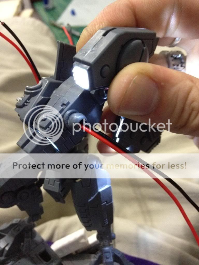
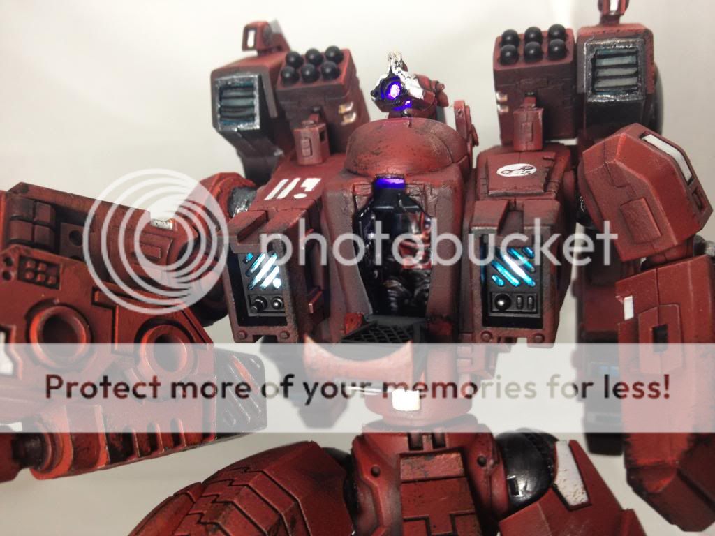
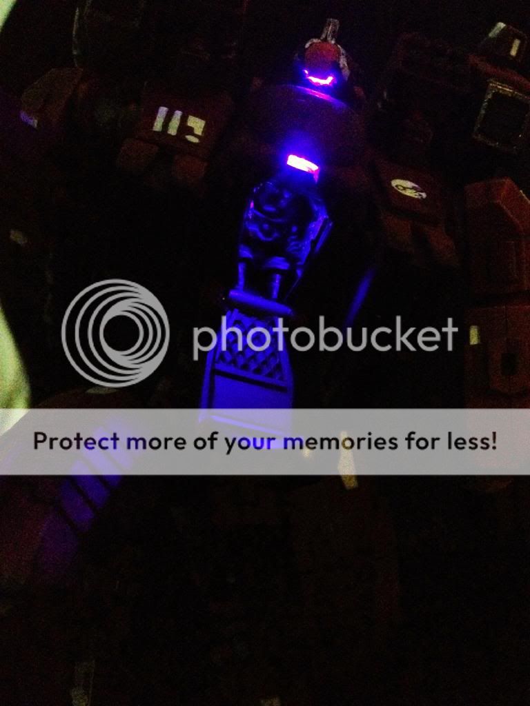
Closed and glowing! The turquoise paint fudges the glow into looking like it is tinted just like I want! Here is where I try not to think about how I'm really not even half-way through the build..

This side shows a lot more of what is going on in this shoulder. It's very busy. One of the main wires will go in on the switch and power the left jetpack. The wires going off screen will route behind the cockpit to the right jetpack so it is in parallel connection with the left (and shares the same switch). The hole in the middle is for the shield wire which will route straight on through the shoulder into the left arm. Excuse the fingernails, but it does help to have longer nails when pushing things into place with hot glue everywhere..
It was nice of them to build the shoulder with connections that fit the wires I need to route. It is a bit of tight fit on the jetpack side of this connection though, so I needed to shave out as much of the spot as possible to get the wires through.
Here the shoulder is coming together. All the wiring is in, everything clears and is glued down, so it is a matter of slowly closing it up without breaking anything. Sometimes you need to push around a wire or cut out some dried glue to force it closed. Having wires cut down to not have too much slack is also key at this stage.
Closed and glowing! The turquoise paint fudges the glow into looking like it is tinted just like I want! Here is where I try not to think about how I'm really not even half-way through the build..
______________________
Left Jetpack
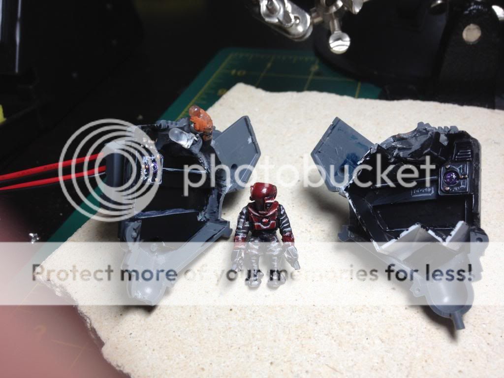
I'm not going to label this out in halves, but that is technically how I do every component here. The outer shell gets coverings over the spots with a light diffusing plastic. I got it from Inventables. It works, but other thin plastic or even paper would do in a pinch. The point was to not make it a big ole' LED showing when you look at it. These pieces were custom trimmed down and tested so that it would connect with the other half no problem. I also painted around the edges with the turquoise.

The other half has all of the real work though. It may not be easy to see, but the two central solder points are the posts from inside the shoulder that are linked with the switch. From these there are three sets of two LED's. One set goes from the black wire to the top back-facing LED, to the Top-front facing LED. Another set is the two bottom back LED's, and the last set is the two bottom front LED's. I left the bottom spot and the side grills on the other half to glow from ambient light rather than their own individual LED, mostly due to room constraints.
The other half has all of the real work though. It may not be easy to see, but the two central solder points are the posts from inside the shoulder that are linked with the switch. From these there are three sets of two LED's. One set goes from the black wire to the top back-facing LED, to the Top-front facing LED. Another set is the two bottom back LED's, and the last set is the two bottom front LED's. I left the bottom spot and the side grills on the other half to glow from ambient light rather than their own individual LED, mostly due to room constraints.


Success!
______________________
Right Jetpack (also cockpit and right shoulder)
Unfortunately I don't have any shots of the head, cockpit, or right should build. They were relatively simple to do, and just a matter of routing the wires where they needed to go. The back neck got some bulking out to cover some of the trailing wire from that particular LED. After that I repeated my left jetpack work on the right side.


______________________
Weapon Arm and Interchangeable Weapon
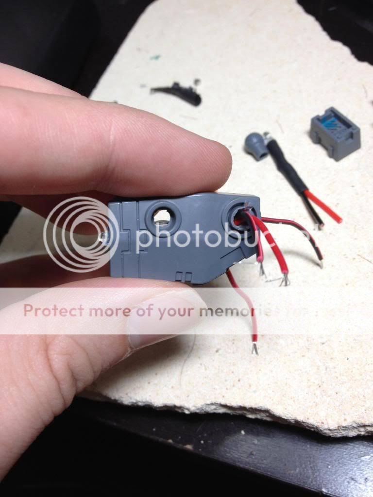
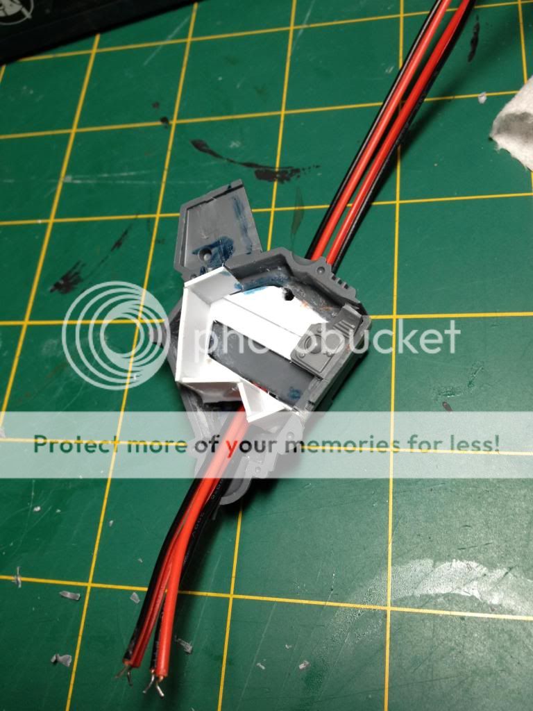
The difficulty of the weapon was going to be a reliable disconnect method that wouldn't break down over time. I got these quick disconnects, and made a hole that matched up with where the weapon connector would be. After it was soldered up, I filled it in with glue to make sure it wouldn't budge. The connection is secure enough that it did not require any extra hold like magnets or pins. You can't quite see it, but the switch for this arm is behind the shoulder bit sticking out.

The weapon was a trial of space and brightness. I played around with a few styles before settling on the one below. You can see I poorly routed my wires, and ended up adding in an extra LED last minute which is why it is such a mess. It took a lot of forcing to get it to close up. I have yet to do the chaingun weapon option, but with this disconnect I can wire it up similarly and hot swap the weapon as needed.
The weapon was a trial of space and brightness. I played around with a few styles before settling on the one below. You can see I poorly routed my wires, and ended up adding in an extra LED last minute which is why it is such a mess. It took a lot of forcing to get it to close up. I have yet to do the chaingun weapon option, but with this disconnect I can wire it up similarly and hot swap the weapon as needed.

______________________
Shield and Front Vent casts
I had originally wanted the shield to be very glowy to show off the force field it issued. As I worked on the design, I toned it down to just the Tau symbol glowing. I felt any more would really pull the attention away from the other parts of the build. To start, I carefully cut out the central symbold circle, leaving the spokes intact on the outer ring.
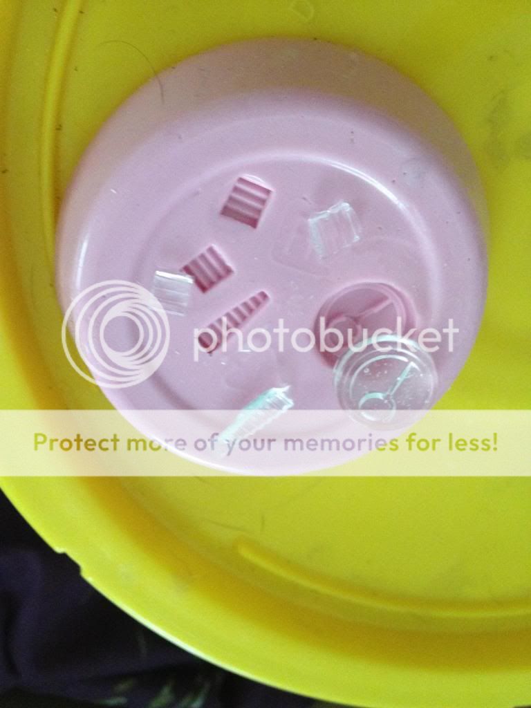
I took the symbol and cleaned up its sides, and then glued it into a container along with my custom vent grills.
I took the symbol and cleaned up its sides, and then glued it into a container along with my custom vent grills.

I used silicone RTV as my mold making material. After mixing it in and resisting the urge to see if it tasted like strawberry yogurt, it was left to set for a day.

Mold came out good, so I mixed up some clear resin and cast out a set of them. After another few days to be sure they were fully set They came out looking good! Only a few air bubbles inside, but no surface flaws.
I worked my wiring down into the left hand, and drilled out the hole for the LED. It is coincidentally the perfect size if you flip the shield-connector bit. I backed the clear symbol with diffusion film, and did a test run.

Looks good!

The wiring on this side was much easier than the rest of the build.

Here it is being assembled. Flipping the shield-connector also makes for a larger amount of light to hit the clear areas.

______________________
Painting and Conclusion
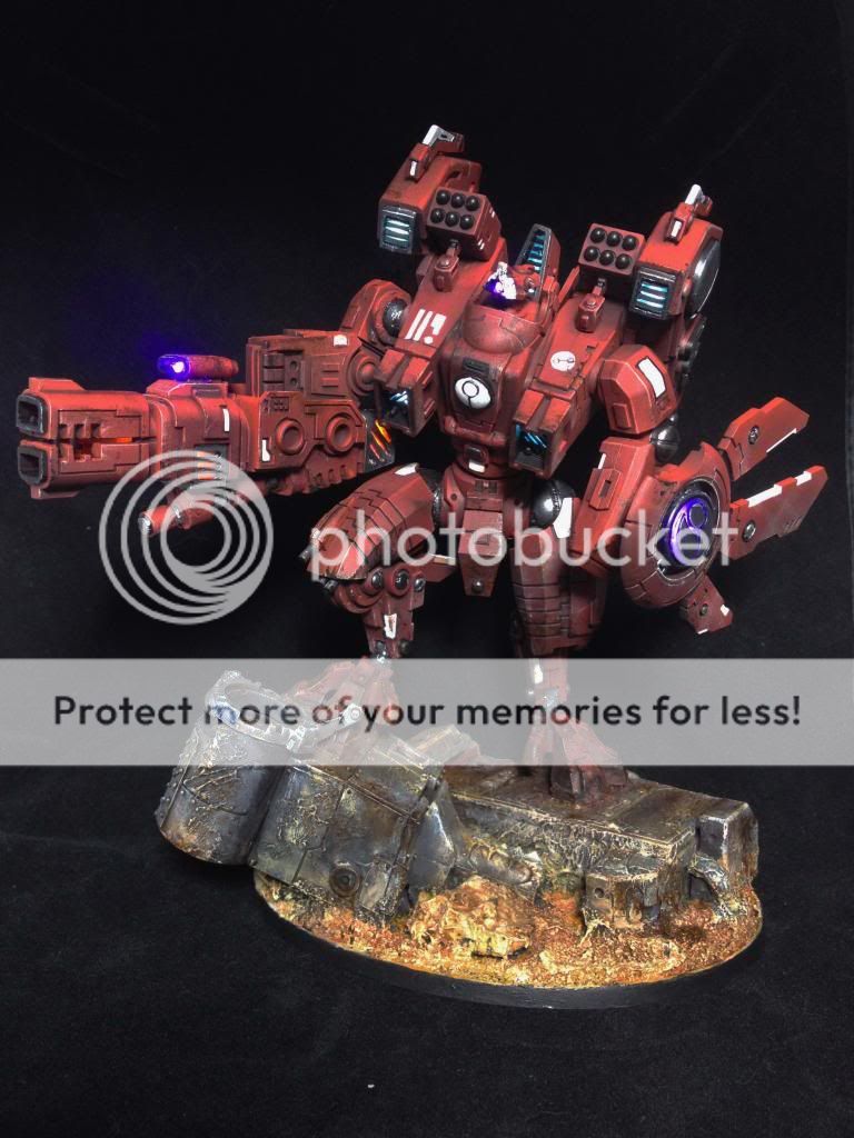
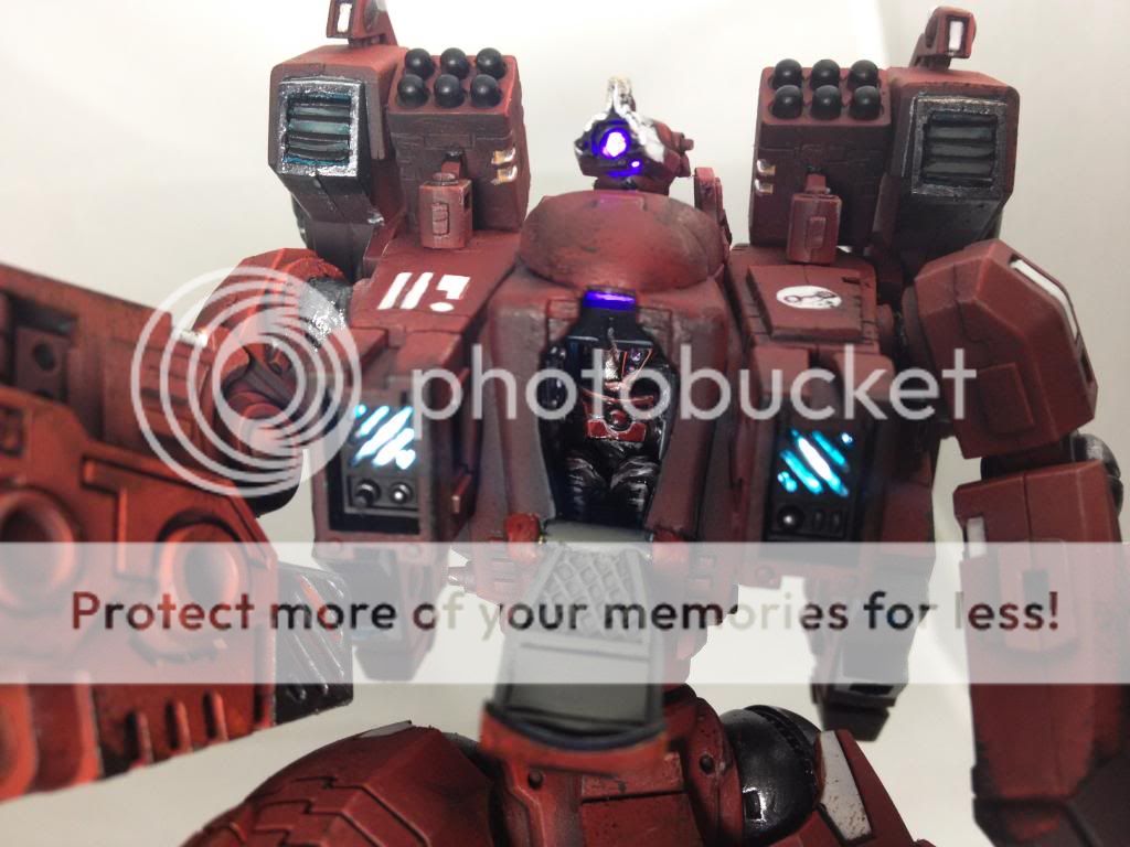
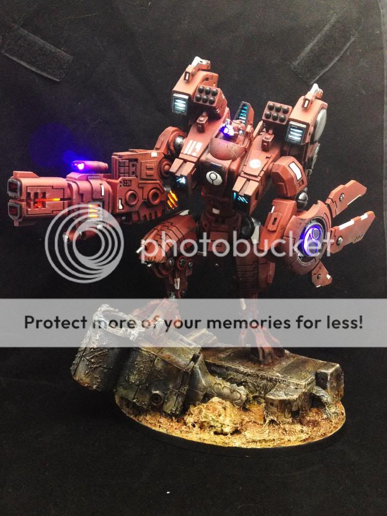
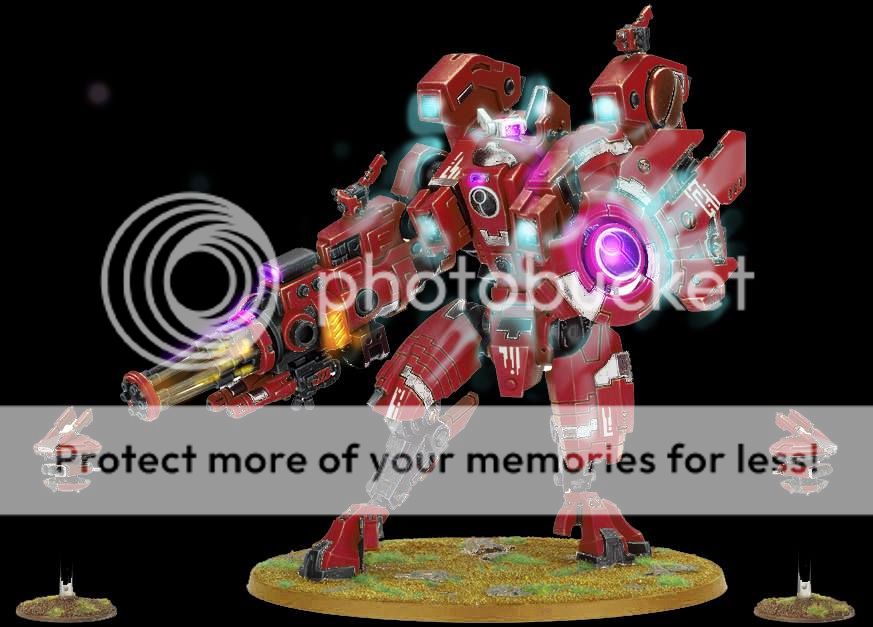
So it finally all came together. At the end I had about a day and a half for painting before the competition deadline. I used tape and sticky tack to block out LED locations, and airbrushed much of the model. I can't say it is my best job, but it was never my intention to go into much more detail. The focus was supposed to stay on the glowing sections, so I feel this was adequate for a final part. I phoned it in on the white locations, and did some half-hearted freehand. Weathering was also pretty simple use of smokey ink and a sponge. I actually think I did a better job with my base painting. I am actually most disappointed in how I did not fix sloppy shoulder joint and ramp hinge glue texturing, and not clearing out a few joining mold lines.
In the end I had just enough time to spend getting good photos before submitting the pics and story requirements for the competition. I placed 5th among many awesome Riptides, and was pleased to have managed to finish this behemoth of a project. I did not procrastinate at all, used 2-3 months of my hobby time entirely on this, and still came right to the wire. I am very glad I stuck with it, but I never want to do something this long again. Heck, even these articles were long to make! Anyways, thanks for reading through, and if you have any questions feel free to ask in the comments.

______________________
Epilogue
... remember when I said I didn't want to do something like this ever again?

I may have misspoken.


.jpeg)


