
When I started brainstorming on my entry to last year's ATT Converted Riptide contest, I quickly realized that I liked the look of the model too much to really go conversion-crazy with it. It would be the first kit I had of it, and possibly the only one. I decided to tweak the design in spots that I disliked, and add to the overall character, rather than drastically change the look of the model. With this in mind, I made my design goals.
Goals
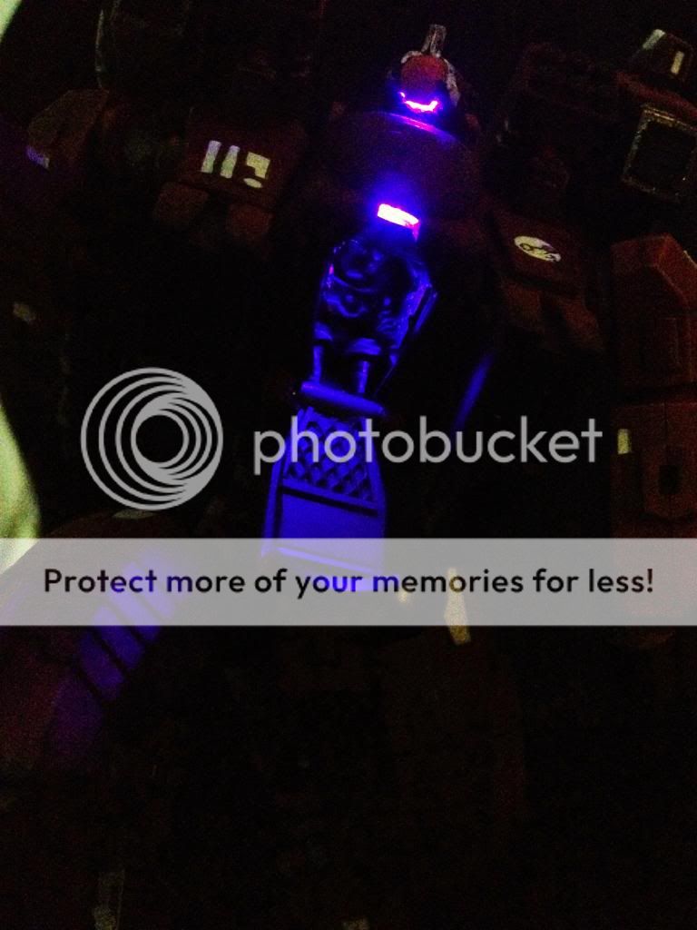
- Glowing parts - I wanted this thing to be glowing like crazy, and show how much my skills have improved since my LED'ed Hammerhead I did many years ago. Glows should not be obviously LEDs. This meant avoiding the common LED colors, and diffusing the glows to hide the telltale LED bulbs. I decided on orange, purple, and a white/cyan to be my main glow choices.
- Novaboost Indicator - I also wanted to be able to show which system was being overboosted on a particular turn, but to also have the whole model on at once. To do this, I had to work out my wiring schematic to incorporate separate parallel sets of series layouts with their own switches.
- Weapon Hot Swap - I wanted a connector set up on the weapon arm to switch between guns and still light them up. Fairly straight forward once the electronics schematic was worked out.
- Vent adjustments - The mold lines on the top vents are horrendous. I imagine they came about after the mold was produced, because there is no other excuse for splitting them down the middle like that. I also knew I would have to edit them anyway if I wanted any glow to come through the vents. I also disliked the skew to the front vents, so they would be tilted to align with the chest connections.
- Pilot and Cockpit - The Riptide is the first Tau model that I could see an internal cockpit in scale with the infantry. I've seen some attempts with normal Crisis suits, but they're just so out of scale that it just doesn't work out to something I would be satisfied with. I had conflicting ideas on whether to put the pilot inside, or have him leaning on the hatch as it is opened. I decided on the pilot inside so that I could put the Riptide in a ready pose that could be perceived in combat, or at rest with the hatch opened up.
- Secondary Weapon Locations - I could not stand the options for the secondary weapon locations. They look tacked on whether on the hand-mount, or sticking up on the tall jet pack. I liked the idea of submarine style vertical rocket firing that would arc back towards it's target. I tried some various styles on the shoulders between the head, but they just didn't look impressive. I went instead for a angled connection between the jets and shoulders that felt a bit more plausible. I also made these permanent rather than interchangeable with plasma, mostly due to time constraints. I could always go back and hack in a magnet system if I ever needed to.
Visual Wound Markers- This was another idea to merge in-game use with appearance. I had figured to have X magnets cut into the hull in spots, which could get a magnet with cotton glued along some wire to show a smoke trail. Each smoke would be a wound. I ran out of time to try this out and cut it from the project.
______________________
Design
______________________
Purchases
I bought my LED's already packaged with resistors for 9V, insulated and wired.Ultimately I would rip a lot of these apart and use them without resistors due to my wiring, but having them ready to test with was helpful in the beginning. I also purchased some switches and a 9V battery housing.
I had previously been pretty poor with soldering, so I spent some more time and money upgrading my setup and learning some better practices in anticipation of all the work I would be doing on this.
______________________
Dryfitting/Posing
The first month was brainstorming, finalizing my internal wiring flow, and buying all the extra parts and tools to complete it. The most I could do was clean up the bits and do some sticky tack dry-fitting. This would all get fine tuned as little problems arose, but helped to keep the overall project moving along as much as possible.
______________________
Ventwork
After removing the old crappy vents, I found a suitable textured plastic sheet from somewhere in my bits box, and cut out some new ones. These would be molded later on to be clear resin, so that I could paint the top parts and leave the bottoms to glow.
I also had plenty of time to work on opening up all of the vents that would not be getting the clearcast treatment. They were drilled into with my pin-vice at the appropriate size. Once I had both ends of a particular grill drilled out, I could use a sharp Exacto to carefully cut through the middle parts. This was one of the many times that having the models in two halves made for a much easier time with modifications. Things like the Cryx Warjacks would never work like this since they are mostly solid resin casts.


Once LED's arrived I could start testing out some of the simpler setups.
The helmet light was just a matter of gutting enough of the head and drilling through the face lens.

I planned to have the thrusters look cyan with a white pure source. I tried painting layers on the white LED, but didn't really get the effects I wanted. Instead I chose to paint the surrounding areas and the diffusion screens the blue coloring to kind of cheat the idea that the light was putting off a colored glow. The result below is pretty close to what I envisioned.

______________________
Cockpit, Hatch, and Pilot
Cockpit: basic design and dry fit cuts, shaving, gluing, contorting ramp work LED work casting: grills shieldI knew that one of the first real assembly steps would have to be the cockpit. I was carving out a believable space filled with controls, a posed pilot inside, and a useable hatch and embark ramp. In addition I needed to effectively light up the space, still cast enough glow out of the cockpit when open, and get a glow on the hatch window when closed. Even more, I needed to route wires from below to the shoulders and around the back. Space inside got cramped very quickly, and I had to rework a few parts to make everything fit.
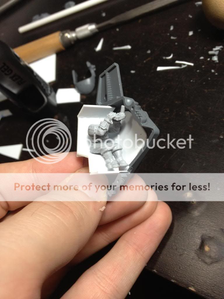
The front was a conveniently separate piece, so it was quickly requisitioned as the hatch. I wanted it to hinge down so it would be the ramp to get in and out of the vehicle.
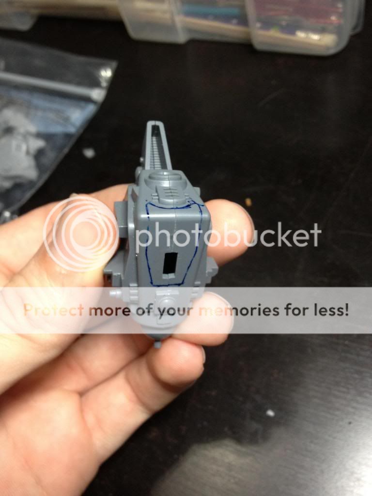
After cutting it out, I did some fine tuning to get the widest looking hole without overstepping the hatch. I threw in my pilot standin to verify the general look.

I added some tubing to be the hinge, which would have some brass rod through it and glued to the hull to be the other half.

With that done, I began playing around with shapes, made a general seat that looked ok, and began shaving it down until it would fit with both halves of the hull together. Not shown are the millions of times I broke the seat while trying to do this. It would have been much easier if I had a more accurate starting width.
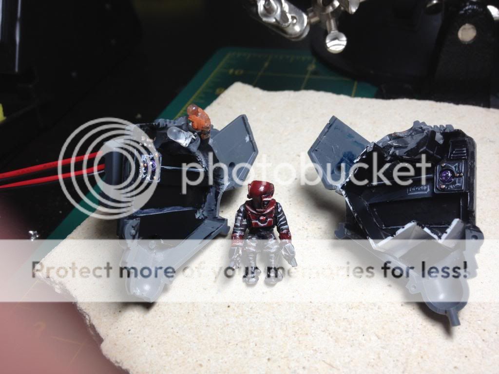
Initial checks with the periscope looked dumb. I chose to switch him out with a Forgeworld Tetra pilot, modified for his serious incline. I also had to cheat and cut a bunch of the back of his helmet to fit him in by the end..

The wires would run around under the left of the pilot, and also behind the seat. The opening in the strip was necessary to fit the pilots arms. I had to have all the initial wiring ready to go, as there wasn't much space to route them once they started multiplying into parallel sets of LED's.
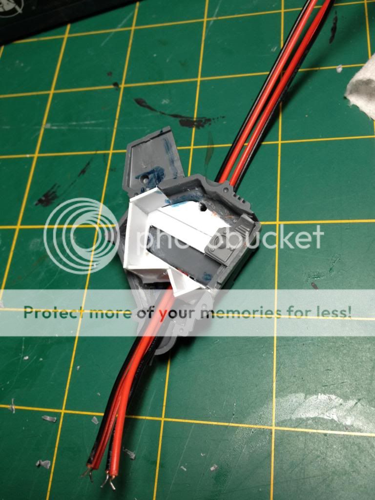
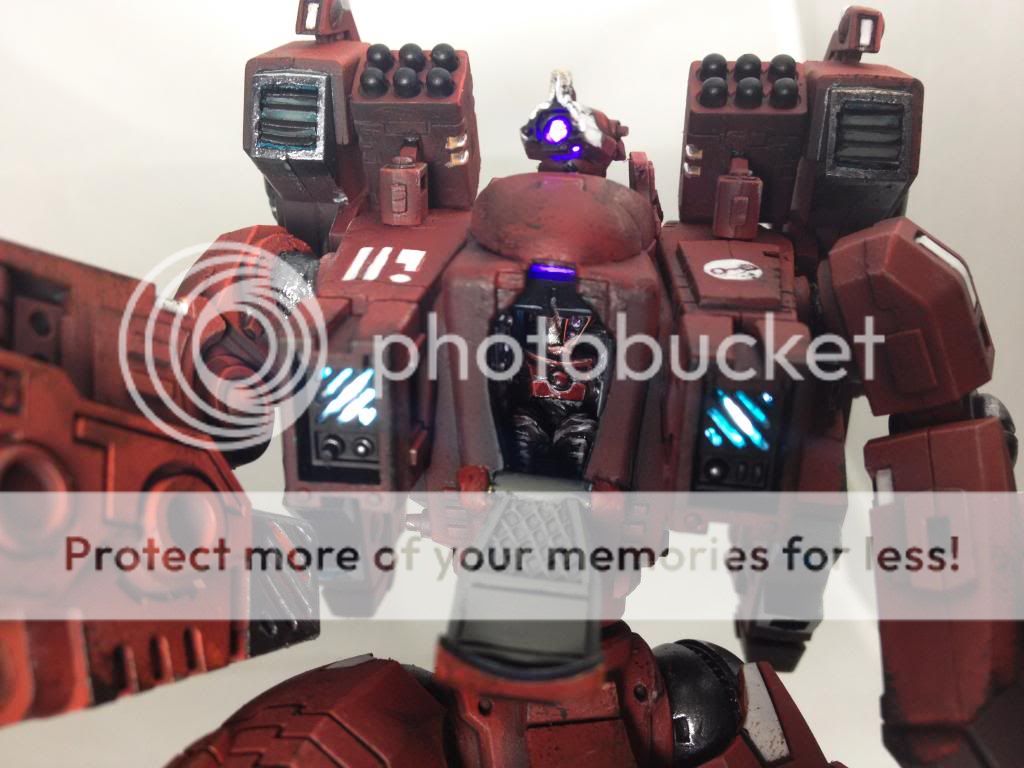
With the basics figured out, I fished around for bits to make the interior more interesting. I think mostly piranha bits reworked, and a space marine heavy pack to be an upper console that would hide the cockpit LED. I cut out the two bullet clip areas of the backpack and put in light diffusing sheets, and eventually did the same to the front part that gaps between the two wall consoles at the top. This would be the area that connects up when the hatch is closed so a bright light would go through the hatch window.

As with any conversion I do, there is no set plan. I start to make things up on the fly and dryfit it. Repeat until it looks good.

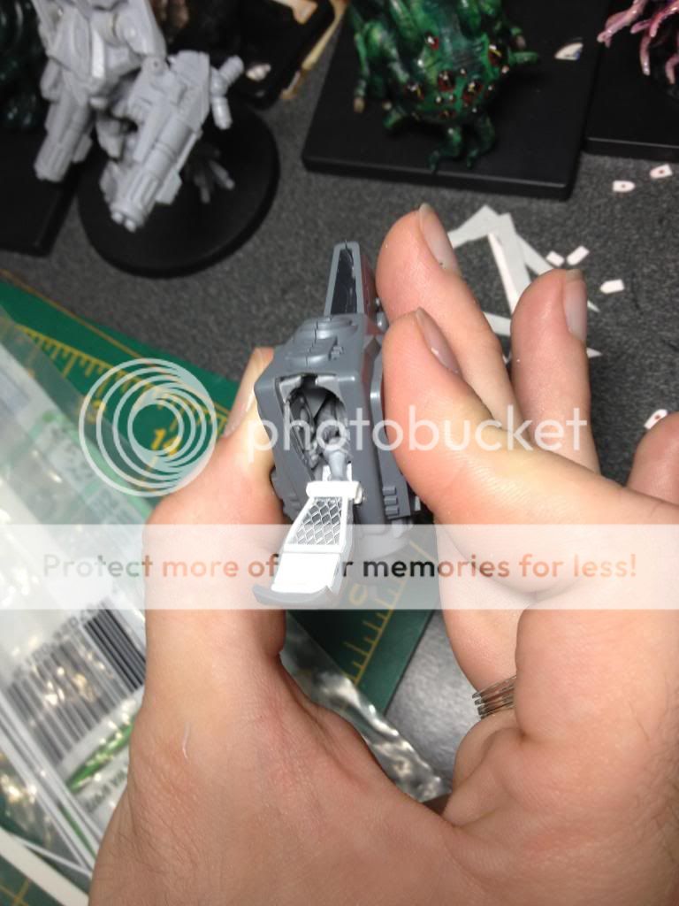
I had to make the hatch interesting, so I took some plasticard strips and winged it. I wanted the bottom half to be more grippy, while the part closer to the hatch window would have to be double-duty of ramp and protection. Part of putting the consoles to the side walls was that the pilot couldn't really have any instruments in front of them if they were going to go stepping on it when its in ramp mode..
Test test test. One of the few times I get to see things actually coming together and working like I imagined.


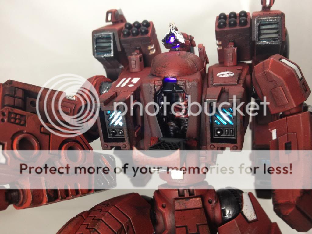
Once it tested to my satisfaction, it was time to paint it up. I went heavy on highlights, as I believed it would help accentuate details in the purple light. While most of the internal wires were routed to the left of the pilot (using his facing), they would also loop around his back to access the interior lights you see below, the right jetpack, and weapon. Did I mention space was tight?
Jumping ahead in the build just to show the completion of the cockpit. I added greenstuff to the front console area to fill in where I overcut, and also to help the hatch stay closed. While it was still curing, I closed the hatch to make the imprints that you can see below, which add a bit of resistance to the hatch opening up on its own. This wouldn't get done at this stage though, because I couldn't actually close the model together yet. I had to wait until the build was halfway complete. You can see what the indents will look like when its finished below. The hinge brass rod was also greenstuffed over. These were not my best works, but I was rushed when it came time to complete them.
______________________
This has made a sizable post, so it is as good as any place to stop for now. The second post will show the steps I took building the finished Riptide, literally from the ground up.
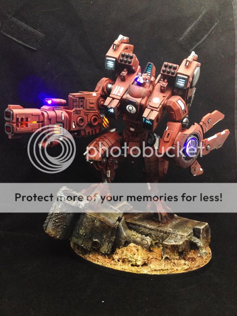
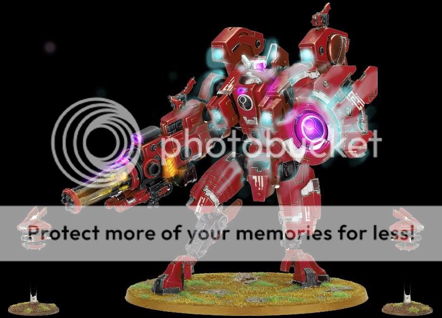
In the meantime, here are a few more shots of the completed project.


.jpeg)


This is really interesting to see how it's actually done. I know how much longer it took to take all these photos and setup an article. Appreciate it! Beautiful model!
ReplyDeleteThanks for the response! It didn't add a whole lot of time to take the pictures, but it does take a presence of mind to remember to take them before moving on. I would like to be able to do this more, but it does prove difficult to do when in the moment.
DeleteIt took me over half a year to start writing up the article though, because I knew it would be a project in itself :]
Best riptide ever.
ReplyDeleteWhere did you get your LEDS? What scale how is it powered?
ReplyDeleteWhere did you get your LEDS? What scale how is it powered?
ReplyDelete